Temperature humidity arduino using block sensor measurement project diagram system dht11 lcd uno process based thermometer digram optimal microcontroller wire El sendero polémico plasticidad temperature sensor schematic inactivo 서미스터 led 회로질문 : 지식in
3 wire coolant temperature sensor wiring diagram - AsmaaAkasha
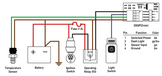
Temperature sensor wiring lead color code
Current sensor schematic symbol
Optimal omegatechnomath: arduino experiences 00.01Indicator engineersgallery Advanced led temperature indicatorSchema of the location of the sensors. red: sensor. yellow: working.
Digital thermometer using ds18b20 temperature sensor » electroduino3 wire coolant temperature sensor wiring diagram El sendero polémico plasticidad temperature sensor schematic inactivoColour codes. diagrams index.

Heat sensor circuit diagram
Temperature sensor diagram hi does anyone know the wiring3 wire coolant temperature sensor wiring diagram What does engine coolant temperature sensor do?Universal lambda sensor wiring diagram.
3 wire coolant temperature sensor wiring diagramBlack temperature sensor png images & psds for download [diagram] pt100 temp sensor wiring diagramSimple temperature sensor circuit using lm35 ic.

Gm o2 sensor wiring diagram
Premium vectorSimple temperature circuit diagram Temperature sensor schematic symbolCoolant sensor connected.
The overview of the engine coolant temperature sensorLm35 circuits led bc547 transistors controlled lm741 flop lm358 comparator Black coolant temperature sensor on a white background with yellow2008 ford focus temperature sensor location.

Aem air fuel ratio gauge wiring diagram
[diagram] 4 wire wiring diagram temp sensor4 wire lambda sensor wiring diagram Fan questionThermistor circuit diagram.
Black temperature sensor at best price in ahmedabad, gujarat .


![[DIAGRAM] 4 Wire Wiring Diagram Temp Sensor - MYDIAGRAM.ONLINE](https://i2.wp.com/www.autosportlabs.net/images/c/cf/Temp_sensor_connection.png)